It is a good idea to sand the bottom of the recess and then re-check the depth against the tenon length. Then repeat the process to turn the other end cap. I left the end caps a little larger in diameter than the case body at this stage and then turned them flush after gluing them on. When gluing the end caps on the cylinder the grain should be aligned so that is going in the same direction on both ends. Glue squeeze out on the inside of the case is very difficult to remove without leaving marks so apply glue only to the outside of the tenon and not inside the recess. Applying wax to the inside ends of the cylinder and to the inside face of the recess will make any squeeze out that does occur easier to clean up.
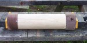
Photo 26: End caps glued and clamped
Once the glue has dried I mount the case back on the lathe and turn the end caps flush with the case body.
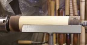
Photo 27: End caps turned flush
Now I have a closed, hollow cylinder. When laying out the cut line for splitting it in half I arranged the cylinder so that I will be cutting along the grain of the end caps. I then used my centre finding square to extend the line across the end of the cylinder.
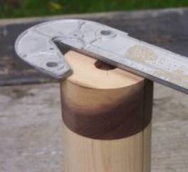
Photo 28: Extend cut line across end
Now it is on to the band saw. I put the cylinder directly behind the blade and carefully adjust my tall fence until the layout line is completely hidden by the blade.
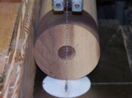
Photo 29: Band saw set-up
I am careful not to rotate the cylinder as I make the cut.
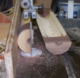
Photo 30: Cut complete
The next step is to dress the just cut edges to remove the saw marks and still have them fit tightly together when the case is closed. I do this on the jointer and that is the reason I oriented the grain on the end caps the way I did. The end caps will be passing across the cutterhead sideways from the way wood is normally presented to the jointer. I set the jointer to take a very light cut and feed the case slowly. It took two passes on each half to remove the saw marks and there was very little tearout at the inside face of the leading end or the outer face of the trailing end.
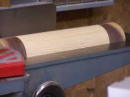
Photo 31: Jointing the edges
I now fit the two halves back together and use a hose clamp in the waste area at each end to prepare for re-mounting on the lathe to turn it back to round. The hose clamp on what will be the drive end is set in about ¼” from the end of the case to give me something to grab with my chuck.
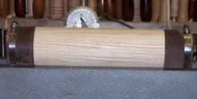
Photo 32: Reassembled and clamped
The original recess that I used to mount the end caps was bored with a forstner bit. The recess is now sort of football shaped because of the material lost to the saw kerf and jointing, but there is just enough left of the dimple from the bit’s centre point to guide me in seating the tail centre point.
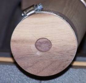
Photo 33: End cap recess