Page 2
I did do a test assembly after cutting the first eight pieces to verify my angles were right. All of the mitres were tight, so I went ahead and cut out the rest of the segments.
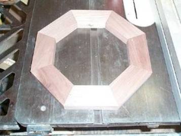
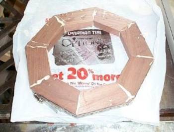
Photo #7: Dry fit of the segments Photo #8: First ring clamped
Since
I had not gotten as far as clearing off my workbench in my brief cleaning
spree, I used the top of my table saw as a flat surface to glue up the
rings. I protected my saw from glue
squeeze out with a plastic shopping bag.
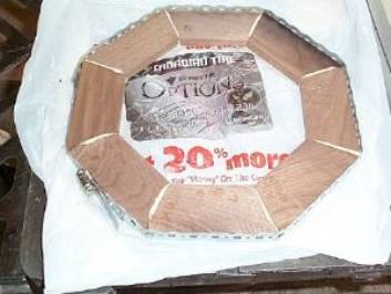
I used some of my custom band clamps to apply pressure when gluing up
the rings.
Photo
#9: One of the ½” thick rings
I
first applied only a little pressure to the band clamp, just enough to draw the
segments together. Then I used a dead
blow mallet to tap each segment down firmly against the saw table before final
tightening of the clamp, to ensure that the assembly would be flat.
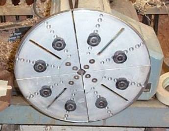
Photo
#10: Jumbo jaws installed on lathe
chuck
I
installed the jumbo jaws on my Oneway scroll chuck to allow mounting the
rings. The rubber dogs on the jumbo
jaws are adjustable to allow gripping of many different diameters, either
internally in “expansion” mode or externally in “compression” mode. These jaws are intended for light cuts on
balanced workpieces turning at 1000 rpm or less.
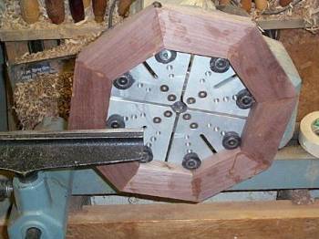
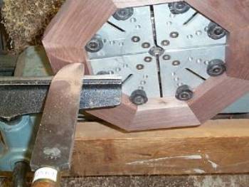
Photo #11: First ring mounted Photo #12: Truing the face
Once the glue had cured, I mounted the first ring on the lathe. I was initially rather hesitant to trust the strength of the glued mitres, but I had no problems with any of the 12 rings I turned. The glue joints stood up to both the expanding pressure of the chuck jaws and the stresses of turning without a single failure. Since these rings are all face grain I was able to get a good surface using scraping techniques to level and true up the faces of the rings.